| Secciones |
|---|
| Foros Electrónica |
|
|
| Boletines de correo |
 |

LM138,LM338
LM138/LM338 5-Amp Adjustable Regulators
Literature Number: SNVS771A
LM138/LM338
5-Amp Adjustable Regulators
General Description
The LM138 series of adjustable 3-terminal positive voltage
regulators is capable of supplying in excess of 5A over a
1.2V to 32V output range. They are exceptionally easy to
use and require only 2 resistors to set the output voltage.
Careful circuit design has resulted in outstanding load and
line regulation comparable to many commercial power
supplies. The LM138 family is supplied in a standard 3-lead
transistor package.
A unique feature of the LM138 family is time-dependent
current limiting. The current limit circuitry allows peak cur-
rents of up to 12A to be drawn from the regulator for short
periods of time. This allows the LM138 to be used with heavy
transient loads and speeds start-up under full-load condi-
tions. Under sustained loading conditions, the current limit
decreases to a safe value protecting the regulator. Also
included on the chip are thermal overload protection and
safe area protection for the power transistor. Overload pro-
tection remains functional even if the adjustment pin is acci-
dentally disconnected.
Normally, no capacitors are needed unless the device is
situated more than 6 inches from the input filter capacitors in
which case an input bypass is needed. An output capacitor
can be added to improve transient response, while bypass-
ing the adjustment pin will increase the regulators ripple
rejection.
Besides replacing fixed regulators or discrete designs, the
LM138 is useful in a wide variety of other applications. Since
the regulator is floating and sees only the input-to-output
differential voltage, supplies of several hundred volts can be
regulated as long as the maximum input to output differential
is not exceeded, i.e., do not short-circuit output to ground.
The part numbers in the LM138 series which have a K suffix
are packaged in a standard Steel TO-3 package, while those
with a T suffix are packaged in a TO-220 plastic package.
The LM138 is rated for -55°C
≤ T
J
≤ +150°C, and the LM338
is rated for 0°C
≤ T
J
≤ +125°C.
Features
n
Guaranteed 7A peak output current
n
Guaranteed 5A output current
n
Adjustable output down to 1.2V
n
Guaranteed thermal regulation
n
Current limit constant with temperature
n
P
+
Product Enhancement tested
n
Output is short-circuit protected
Applications
n
Adjustable power supplies
n
Constant current regulators
n
Battery chargers
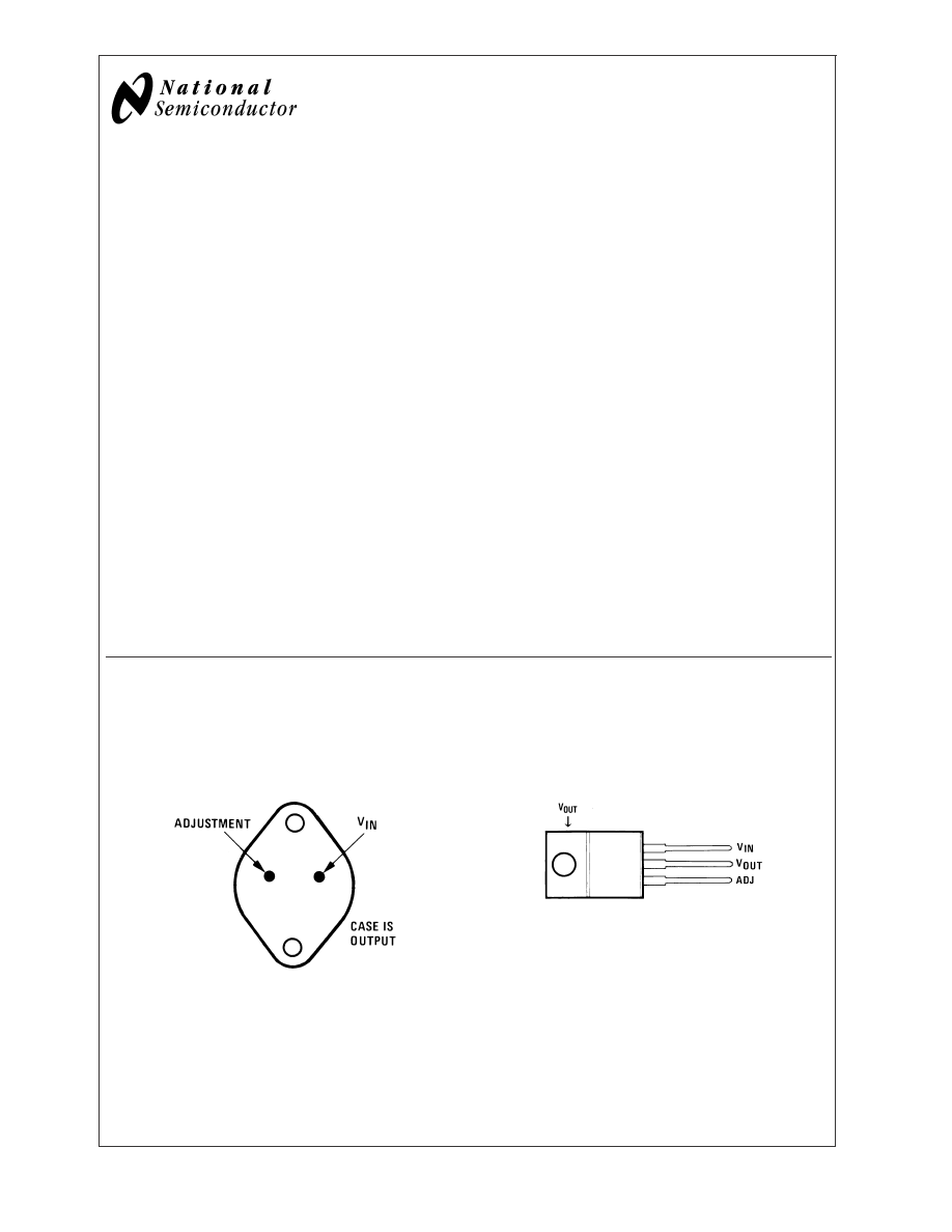
Connection Diagrams
(See Physical Di-
mension section for further information)
Connection Diagrams
(TO-3 STEEL)
Metal Can Package
(TO-220)
Plastic Package
00906030
Bottom View
Order Number LM138K STEEL or LM338K STEEL
See NS Package Number K02A
00906031
Front View
Order Number LM338T
See NS Package Number T03B
May 1998
LM138/LM338
5-Amp
Adjustable
Regulators
© 2004 National Semiconductor Corporation
DS009060
www.national.com
Absolute Maximum Ratings
If Military/Aerospace specified devices are required,
please contact the National Semiconductor Sales Office/
Distributors for availability and specifications.
Power Dissipation
Internally
limited
Input/Output Voltage Differential
+40V, -0.3V
Storage Temperature
-65°C to
+150°C
Lead Temperature
Metal Package (Soldering, 10
seconds)
Plastic Package (Soldering, 4
seconds)
300°C
260°C
ESD Tolerance
TBD
Operating Temperature Range
LM138
-55°C
≤ T
J
≤ +150°C
LM338
0°C
≤ T
J
≤ +125°C
Electrical Characteristics
Specifications with standard type face are for T
J
= 25°C, and those with boldface type apply over full Operating Tempera-
ture Range. Unless otherwise specified, V
IN
- V
OUT
= 5V; and I
OUT
= 10 mA.
Symbol
Parameter
Conditions
LM138
Units
Min
Typ
Max
V
REF
Reference Voltage
3V
≤ (V
IN
- V
OUT
)
≤ 35V,
1.19
1.24
1.29
V
10 mA
≤ I
OUT
≤ 5A, P ≤ 50W
V
RLINE
Line Regulation
3V
≤ (V
IN
- V
OUT
)
≤ 35V
0.005
0.01
%/V
0.02
0.04
%/V
V
RLOAD
Load Regulation
10 mA
≤ I
OUT
≤ 5A
0.1
0.3
%
0.3
0.6
%
Thermal Regulation
20 ms Pulse
0.002
0.01
%/W
I
ADJ
Adjustment Pin Current
45
100
µA
∆I
ADJ
Adjustment Pin Current Change
10 mA
≤ I
OUT
≤ 5A,
0.2
5
µA
3V
≤ (V
IN
- V
OUT
)
≤ 35V
∆V
R/T
Temperature Stability
T
MIN
≤ T
J
≤ T
MAX
1
%
I
LOAD
(Min)
Minimum Load Current
V
IN
- V
OUT
= 35V
3.5
5
mA
I
CL
Current Limit
V
IN
- V
OUT
≤ 10V
DC
5
8
A
0.5 ms Peak
7
12
A
V
IN
- V
OUT
= 30V
1
1
A
V
N
RMS Output Noise, % of V
OUT
10 Hz
≤ f ≤ 10 kHz
0.003
%
Ripple Rejection Ratio
V
OUT
= 10V, f = 120 Hz, C
ADJ
= 0 µF
60
dB
V
OUT
= 10V, f = 120 Hz, C
ADJ
= 10 µF
60
75
dB
Long-Term Stability
T
J
= 125°C, 1000 Hrs
0.3
1
%
Θ
JC
Thermal Resistance,
K Package
1
°C/W
Junction to Case
Θ
JA
Thermal Resistance, Junction to
K Package
35
°C/W
Ambient (No Heat Sink)
Electrical Characteristics
Symbol
Parameter
Conditions
LM338
Units
Min
Typ
Max
V
REF
Reference Voltage
3V
≤ (V
IN
- V
OUT
)
≤ 35V,
1.19
1.24
1.29
V
10 mA
≤ I
OUT
≤ 5A, P ≤ 50W
V
RLINE
Line Regulation
3V
≤ (V
IN
- V
OUT
)
≤ 35V
0.005
0.03
%/V
0.02
0.06
%/V
V
RLOAD
Load Regulation
10 mA
≤ I
OUT
≤ 5A
0.1
0.5
%
0.3
1
%
LM138/LM338
www.national.com
2
Electrical Characteristics
(Continued)
Symbol
Parameter
Conditions
LM338
Units
Min
Typ
Max
Thermal Regulation
20 ms Pulse
0.002
0.02
%/W
I
ADJ
Adjustment Pin Current
45
100
µA
∆I
ADJ
Adjustment Pin Current Change
10 mA
≤ I
OUT
≤ 5A,
3V
≤ (V
IN
- V
OUT
)
≤ 35V
0.2
5
µA
∆V
R/T
Temperature Stability
T
MIN
≤ T
J
≤ T
MAX
1
%
I
LOAD
(Min)
Minimum Load Current
V
IN
- V
OUT
= 35V
3.5
10
mA
I
CL
Current Limit
V
IN
- V
OUT
≤ 10V
DC
5
8
A
0.5 ms Peak
7
12
A
V
IN
- V
OUT
= 30V
1
A
V
N
RMS Output Noise, % of V
OUT
10 Hz
≤ f ≤ 10 kHz
0.003
%
Ripple Rejection Ratio
V
OUT
= 10V, f = 120 Hz, C
ADJ
= 0 µF
60
dB
V
OUT
= 10V, f = 120 Hz, C
ADJ
= 10 µF
60
75
dB
Long-Term Stability
T
J
= 125°C, 1000 hrs
0.3
1
%
Θ
JC
Thermal Resistance
K Package
1
°C/W
Junction to Case
T Package
4
°C/W
Θ
JA
Thermal Resistance, Junction to
K Package
35
°C/W
Ambient (No Heat Sink)
T Package
50
°C/W
Note 1: Absolute Maximum Ratings indicate limits beyond which damage to the device may occur. Operating Ratings indicate conditions for which the device is
intended to be functional, but do not guarantee specific performance limits. For guaranteed specifications and test conditions, see the Electrical Characteristics.
Note 2: These specifications are applicable for power dissipations up to 50W for the TO-3 (K) package and 25W for the TO-220 (T) package. Power dissipation is
guaranteed at these values up to 15V input-output differential. Above 15V differential, power dissipation will be limited by internal protection circuitry. All limits (i.e.,
the numbers in the Min. and Max. columns) are guaranteed to Nationals AOQL (Average Outgoing Quality Level).
Note 3: Regulation is measured at a constant junction temperature, using pulse testing with a low duty cycle. Changes in output voltage due to heating effects are
covered under the specifications for thermal regulation.
Note 4: Refer to RETS138K drawing for military specifications of LM138K.
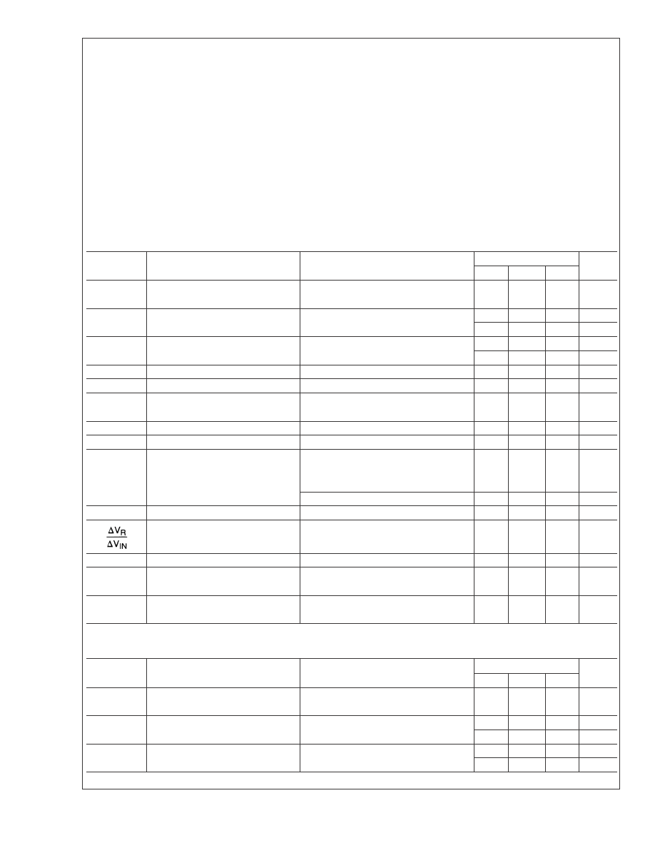
Typical Performance Characteristics
Current Limit
Current Limit
00906032
00906033
LM138/LM338
www.national.com
3
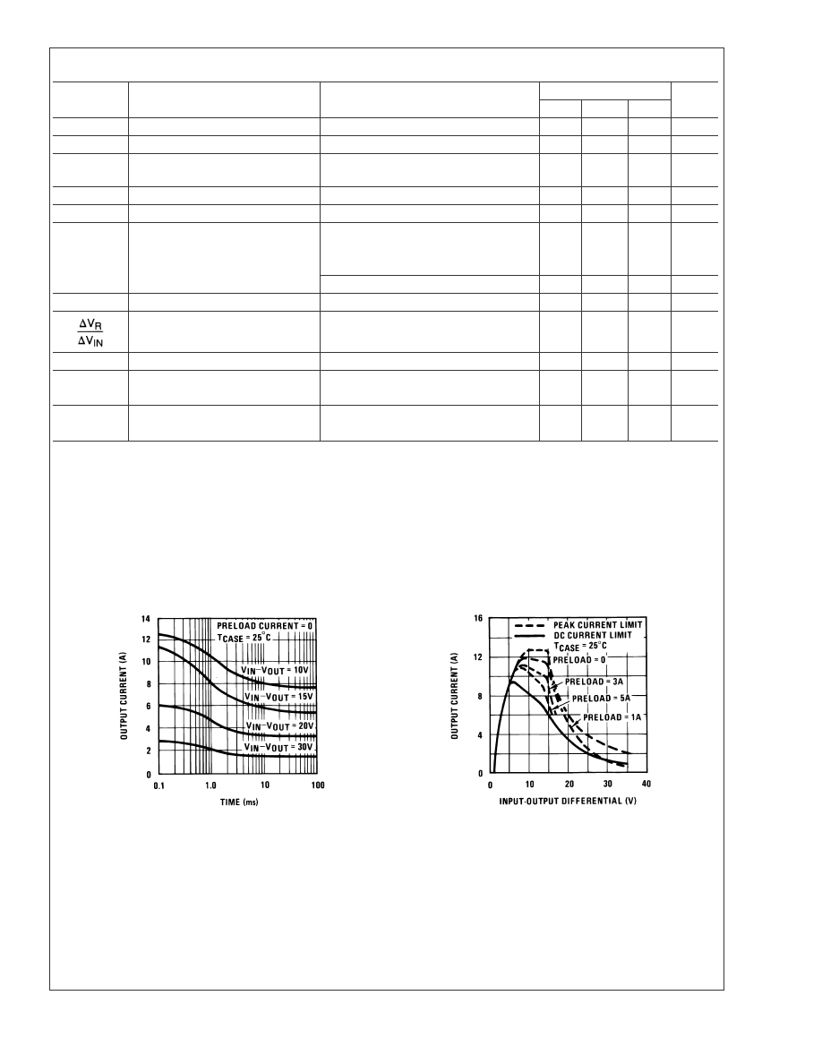
Typical Performance Characteristics
(Continued)
Current Limit
Load Regulation
00906034
00906035
Dropout Voltage
Adjustment
Current
00906036
00906037
Temperature Stability
Output Impedance
00906038
00906039
LM138/LM338
www.national.com
4
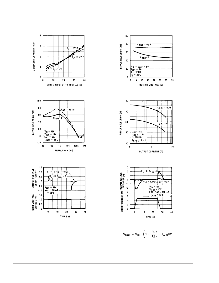
Typical Performance Characteristics
(Continued)
Minimum Operating
Current
Ripple Rejection
00906040
00906041
Ripple Rejection
Ripple Rejection
00906042
00906043
Line Transient Response
Load Transient Response
00906044
00906045
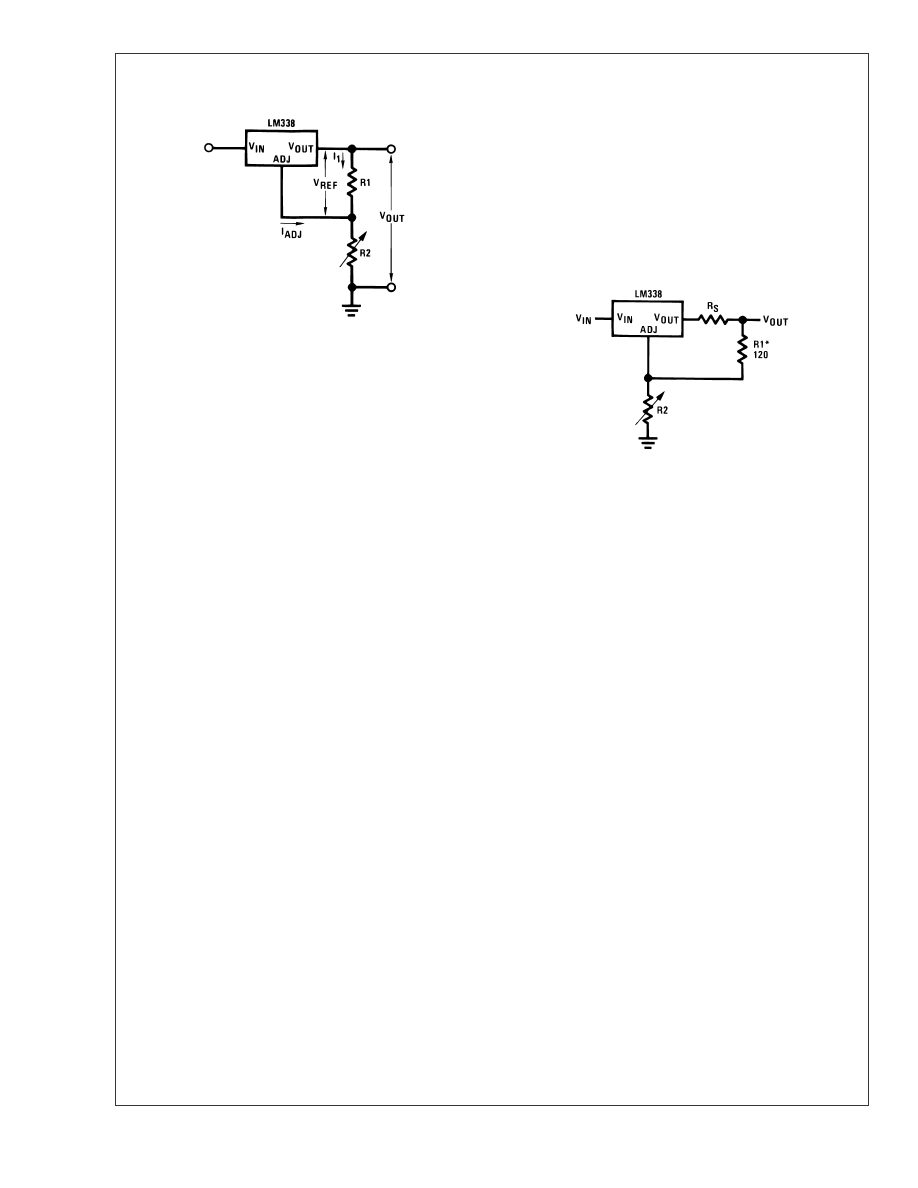
Application Hints
In operation, the LM138 develops a nominal 1.25V reference
voltage, V
REF
, between the output and adjustment terminal.
The reference voltage is impressed across program resistor
R1 and, since the voltage is constant, a constant current I
1
then flows through the output set resistor R2, giving an
output voltage of
LM138/LM338
www.national.com
5
Application Hints
(Continued)
Since the 50 µA current from the adjustment terminal repre-
sents an error term, the LM138 was designed to minimize
I
ADJ
and make it very constant with line and load changes.
To do this, all quiescent operating current is returned to the
output establishing a minimum load current requirement. If
there is insufficient load on the output, the output will rise.
EXTERNAL CAPACITORS
An input bypass capacitor is recommended. A 0.1 µF disc or
1 µF solid tantalum on the input is suitable input bypassing
for almost all applications. The device is more sensitive to
the absence of input bypassiing when adjustment or output
capacitors are used but the above values will eliminate the
possiblity of problems.
The adjustment terminal can be bypassed to ground on the
LM138 to improve ripple rejection. This bypass capacitor
prevents ripple from being amplified as the output voltage is
increased. With a 10 µF bypass capacitor 75 dB ripple
rejection is obtainable at any output level. Increases over 20
µF do not appreciably improve the ripple rejection at fre-
quencies above 120 Hz. If the bypass capacitor is used, it is
sometimes necessary to include protection diodes to prevent
the capacitor from discharging through internal low current
paths and damaging the device.
In general, the best type of capacitors to use are solid
tantalum. Solid tantalum capacitors have low impedance
even at high frequencies. Depending upon capacitor con-
struction, it takes about 25 µF in aluminum electrolytic to
equal 1 µF solid tantalum at high frequencies. Ceramic
capacitors are also good at high frequencies; but some types
have a large decrease in capacitance at frequencies around
0.5 MHz. For this reason, 0.01 µF disc may seem to work
better than a 0.1 µF disc as a bypass.
Although the LM138 is stable with no output capacitors, like
any feedback circuit, certain values of external capacitance
can cause excessive ringing. This occurs with values be-
tween 500 pF and 5000 pF. A 1 µF solid tantalum (or 25 µF
aluminum electrolytic) on the output swamps this effect and
insures stability.
LOAD REGULATION
The LM138 is capable of providing extremely good load
regulation but a few precautions are needed to obtain maxi-
mum performance. The current set resistor connected be-
tween the adjustment terminal and the output terminal (usu-
ally 240
Ω¦) should be tied directly to the output of the
regulator (case) rather than near the load. This eliminates
line drops from appearing effectively in series with the refer-
ence and degrading regulation. For example, a 15V regula-
tor with 0.05
Ω¦ resistance between the regulator and load will
have a load regulation due to line resistance of 0.05
Ω¦ x I
L
. If
the set resistor is connected near the load the effective line
resistance will be 0.05
Ω¦ (1 + R2/R1) or in this case, 11.5
times worse.
shows the effect of resistance between the regula-
tor and 240
Ω¦ set resistor.
With the TO-3 package, it is easy to minimize the resistance
from the case to the set resistor, by using 2 separate leads to
the case. The ground of R2 can be returned near the ground
of the load to provide remote ground sensing and improve
load regulation.
PROTECTION DIODES
When external capacitors are used with any IC regulator it is
sometimes necessary to add protection diodes to prevent
the capacitors from discharging through low current points
into the regulator. Most 20 µF capacitors have low enough
internal series resistance to deliver 20A spikes when
shorted. Although the surge is short, there is enough energy
to damage parts of the IC.
When an output capacitor is connected to a regulator and
the input is shorted, the output capacitor will discharge into
the output of the regulator. The discharge current depends
on the value of the capacitor, the output voltage of the
regulator, and the rate of decrease of V
IN
. In the LM138 this
discharge path is through a large junction that is able to
sustain 25A surge with no problem. This is not true of other
types of positive regulators. For output capacitors of 100 µF
or less at output of 15V or less, there is no need to use
diodes.
The bypass capacitor on the adjustment terminal can dis-
charge through a low current junction. Discharge occurs
when either the input or output is shorted. Internal to the
LM138 is a 50
Ω¦ resistor which limits the peak discharge
current. No protection is needed for output voltages of 25V
or less and 10 µF capacitance. shows an LM138
with protection diodes included for use with outputs greater
than 25V and high values of output capacitance.
00906006
FIGURE 1.
00906007
FIGURE 2. Regulator with Line
Resistance in Output Lead
LM138/LM338
www.national.com
6
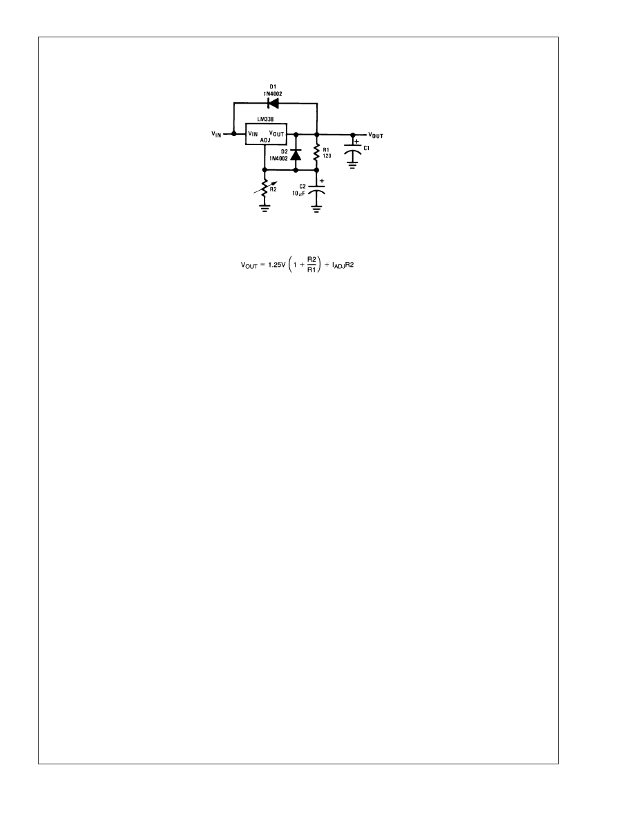
Application Hints
(Continued)
00906008
D1 protects against C1
D2 protects against C2
FIGURE 3. Regulator with Protection Diodes
LM138/LM338
www.national.com
7
Typical Applications
Regulator and Voltage Reference
1.2V-25V Adjustable Regulator
00906003
00906001
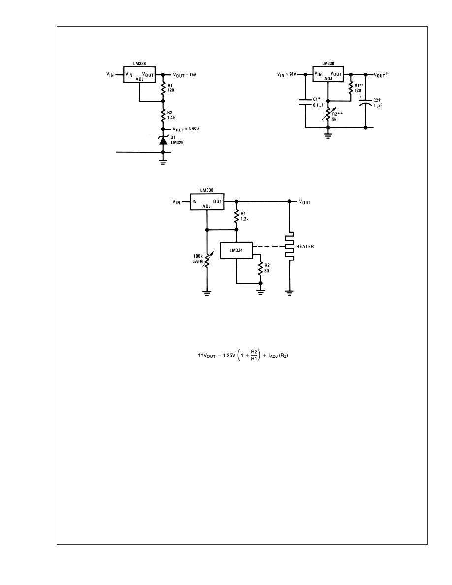
Temperature Controller
00906010
Full output current not available
at high input-output voltages
Optional improves transient response. Output capacitors in the range of 1 µF to 1000 µF of aluminum or tantalum electrolytic are commonly used to provide
improved output impedance and rejection of transients.
*Needed if device is more than 6 inches from filter capacitors.
**R1 = 240
Ω¦ for LM138. R1, R2 as an assembly can be ordered from Bourns:
MIL part no. 7105A-AT2-502
COMM part no. 7105A-AT7-502
LM138/LM338
www.national.com
8
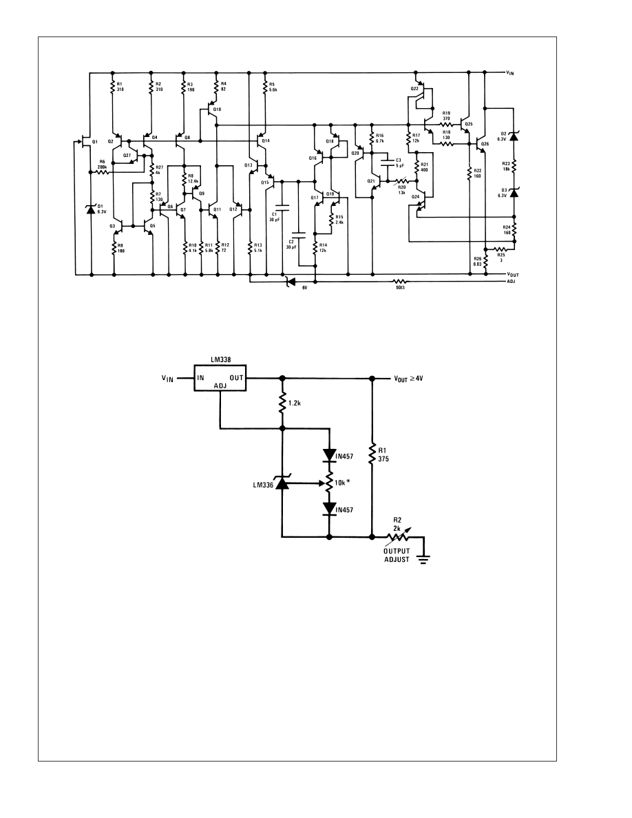
Schematic Diagram
00906009
Typical Applications
Precision Power Regulator with Low Temperature Coefficient
00906012
* Adjust for 3.75 across R1
LM138/LM338
www.national.com
9
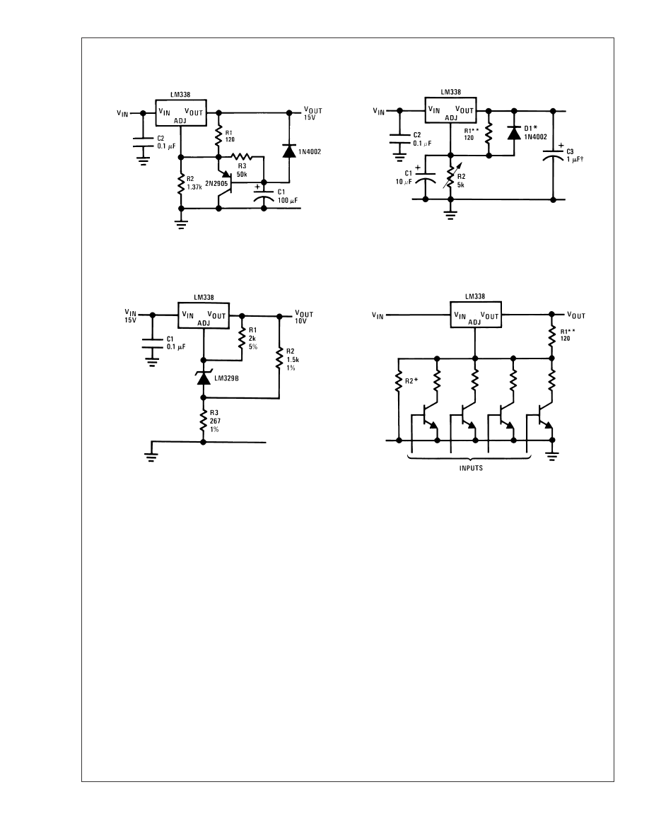
Typical Applications
(Continued)
Slow Turn-On 15V Regulator
Adjustable Regulator with Improved Ripple Rejection
00906013
00906014
Solid tantalum
*Discharges C1 if output is shorted to ground
**R1 = 240
Ω¦ for LM138
High Stability 10V Regulator
Digitally Selected Outputs
00906015
00906016
*Sets maximum V
OUT
**R1 = 240
Ω¦ for LM138
LM138/LM338
www.national.com
10
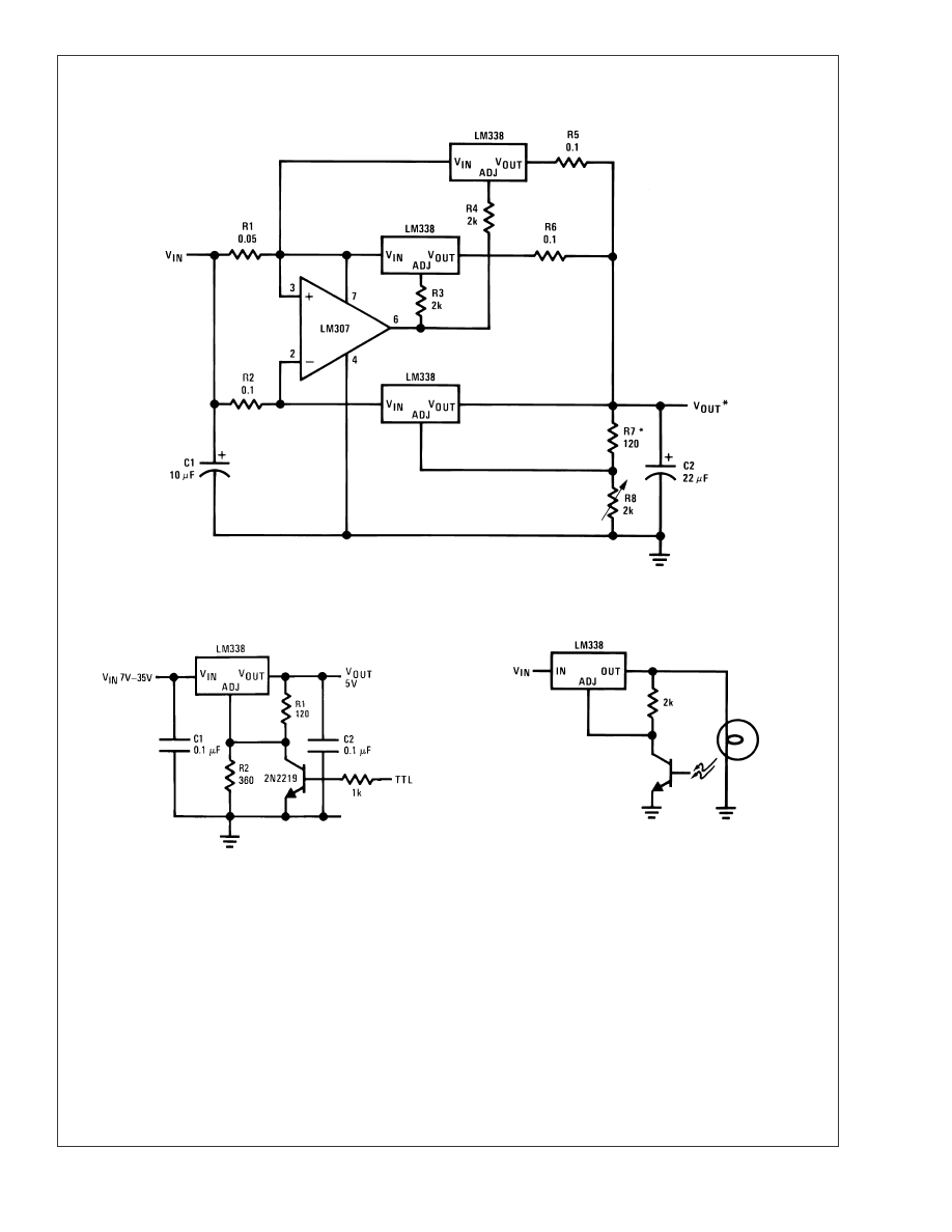
Typical Applications
(Continued)
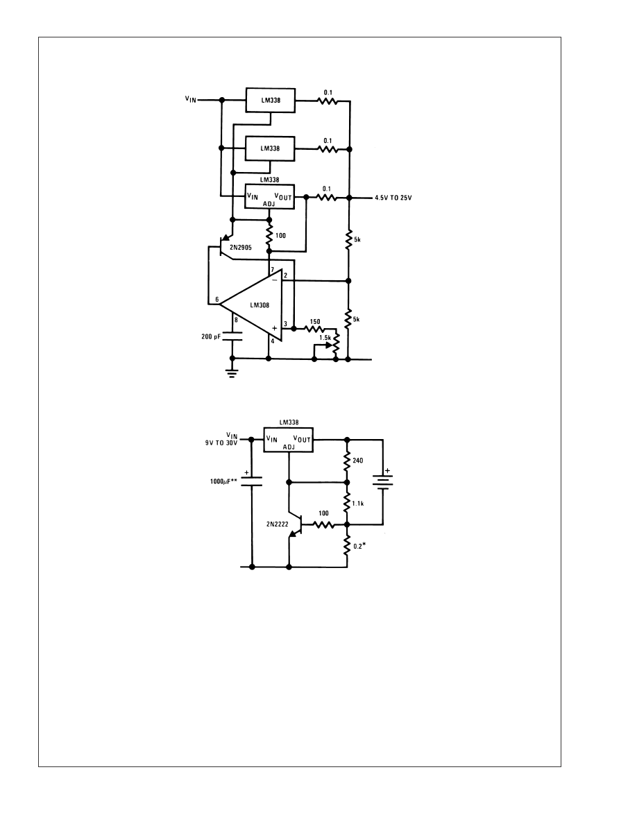
15A Regulator
00906017
* Minimum load 100 mA
5V Logic Regulator with Electronic Shutdown**
Light Controller
00906018
** Minimum output
1.2V
00906011
LM138/LM338
www.national.com
11
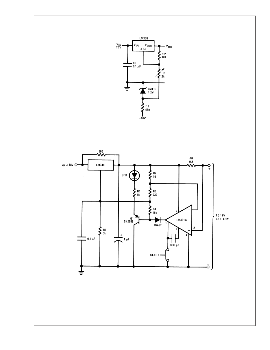
Typical Applications
(Continued)
0 to 22V Regulator
00906019
* R1 = 240
Ω¦, R2 = 5k for LM138
Full output current not available
at high input-output voltages
12V Battery Charger
00906020
LM138/LM338
www.national.com
12

Typical Applications
(Continued)
Adjustable Current Regulator
Precision Current Limiter
00906021
00906022
5A Current Regulator
Tracking Preregulator
00906023
00906024
Adjusting Multiple On-Card Regulators with Single Control*
00906025
Minimum load 10 mA
* All outputs within
±
100 mV
LM138/LM338
www.national.com
13
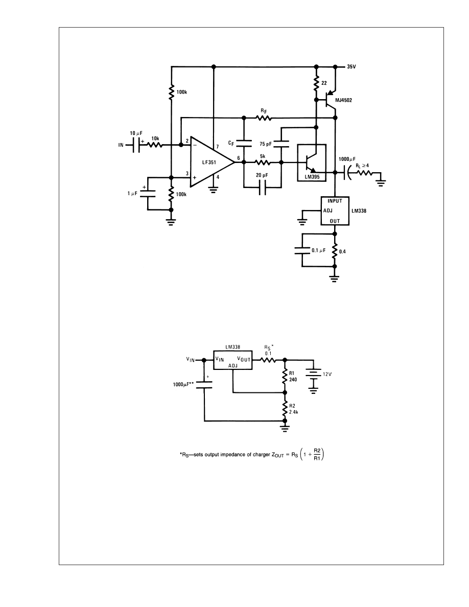
Typical Applications
(Continued)
Power Amplifier
00906027
A
V
= 1, R
F
= 10k, C
F
= 100 pF
A
V
= 10, R
F
= 100k, C
F
= 10 pF
Bandwidth
≥ 100 kHz
Distortion
≤ 0.1%
Simple 12V Battery Charger
00906028
Use of R
S
allows low charging rates with fully charged battery.
**The 1000 µF is recommended to filter out input transients
LM138/LM338
www.national.com
14
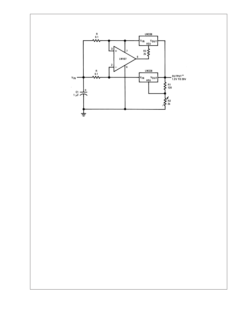
Typical Applications
(Continued)
Adjustable 15A Regulator
00906026
Current Limited 6V Charger
00906029
* Set max charge current to 3A
** THE 1000 µF is recommended to filter out input transients.
LM138/LM338
www.national.com
15
Typical Applications
(Continued)
10A Regulator
00906002
* Minimum load 100 mA
LM138/LM338
www.national.com
16
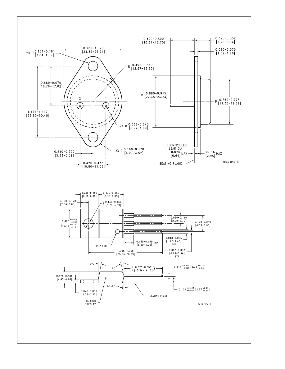
Physical Dimensions
inches (millimeters)
unless otherwise noted
2 Lead TO-3 Metal Can Package (K)
Order Number LM138K or LM338K STEEL
NS Package Number K02A
3 Lead Molded TO-220 (T)
Order Number LM338T
NS Package Number T03B
LM138/LM338
www.national.com
17
Notes
National does not assume any responsibility for use of any circuitry described, no circuit patent licenses are implied and National reserves
the right at any time without notice to change said circuitry and specifications.
For the most current product information visit us at www.national.com.
LIFE SUPPORT POLICY
NATIONALS PRODUCTS ARE NOT AUTHORIZED FOR USE AS CRITICAL COMPONENTS IN LIFE SUPPORT DEVICES OR SYSTEMS
WITHOUT THE EXPRESS WRITTEN APPROVAL OF THE PRESIDENT AND GENERAL COUNSEL OF NATIONAL SEMICONDUCTOR
CORPORATION. As used herein:
1. Life support devices or systems are devices or systems
which, (a) are intended for surgical implant into the body, or
(b) support or sustain life, and whose failure to perform when
properly used in accordance with instructions for use
provided in the labeling, can be reasonably expected to result
in a significant injury to the user.
2. A critical component is any component of a life support
device or system whose failure to perform can be reasonably
expected to cause the failure of the life support device or
system, or to affect its safety or effectiveness.
BANNED SUBSTANCE COMPLIANCE
National Semiconductor certifies that the products and packing materials meet the provisions of the Customer Products Stewardship
Specification (CSP-9-111C2) and the Banned Substances and Materials of Interest Specification (CSP-9-111S2) and contain no Banned
Substances as defined in CSP-9-111S2.
National Semiconductor
Americas Customer
Support Center
Email: new.feedback@nsc.com
Tel: 1-800-272-9959
National Semiconductor
Europe Customer Support Center
Fax: +49 (0) 180-530 85 86
Email: europe.support@nsc.com
Deutsch Tel: +49 (0) 69 9508 6208
English
Tel: +44 (0) 870 24 0 2171
Français Tel: +33 (0) 1 41 91 8790
National Semiconductor
Asia Pacific Customer
Support Center
Email: ap.support@nsc.com
National Semiconductor
Japan Customer Support Center
Fax: 81-3-5639-7507
Email: jpn.feedback@nsc.com
Tel: 81-3-5639-7560
www.national.com
LM138/LM338
5-Amp
Adjustable
Regulators

IMPORTANT NOTICE
Texas Instruments Incorporated and its subsidiaries (TI) reserve the right to make corrections, modifications, enhancements, improvements,
and other changes to its products and services at any time and to discontinue any product or service without notice. Customers should
obtain the latest relevant information before placing orders and should verify that such information is current and complete. All products are
sold subject to TI
s terms and conditions of sale supplied at the time of order acknowledgment.
TI warrants performance of its hardware products to the specifications applicable at the time of sale in accordance with TI
s standard
warranty. Testing and other quality control techniques are used to the extent TI deems necessary to support this warranty. Except where
mandated by government requirements, testing of all parameters of each product is not necessarily performed.
TI assumes no liability for applications assistance or customer product design. Customers are responsible for their products and
applications using TI components. To minimize the risks associated with customer products and applications, customers should provide
adequate design and operating safeguards.
TI does not warrant or represent that any license, either express or implied, is granted under any TI patent right, copyright, mask work right,
or other TI intellectual property right relating to any combination, machine, or process in which TI products or services are used. Information
published by TI regarding third-party products or services does not constitute a license from TI to use such products or services or a
warranty or endorsement thereof. Use of such information may require a license from a third party under the patents or other intellectual
property of the third party, or a license from TI under the patents or other intellectual property of TI.
Reproduction of TI information in TI data books or data sheets is permissible only if reproduction is without alteration and is accompanied
by all associated warranties, conditions, limitations, and notices. Reproduction of this information with alteration is an unfair and deceptive
business practice. TI is not responsible or liable for such altered documentation. Information of third parties may be subject to additional
restrictions.
Resale of TI products or services with statements different from or beyond the parameters stated by TI for that product or service voids all
express and any implied warranties for the associated TI product or service and is an unfair and deceptive business practice. TI is not
responsible or liable for any such statements.
TI products are not authorized for use in safety-critical applications (such as life support) where a failure of the TI product would reasonably
be expected to cause severe personal injury or death, unless officers of the parties have executed an agreement specifically governing
such use. Buyers represent that they have all necessary expertise in the safety and regulatory ramifications of their applications, and
acknowledge and agree that they are solely responsible for all legal, regulatory and safety-related requirements concerning their products
and any use of TI products in such safety-critical applications, notwithstanding any applications-related information or support that may be
provided by TI. Further, Buyers must fully indemnify TI and its representatives against any damages arising out of the use of TI products in
such safety-critical applications.
TI products are neither designed nor intended for use in military/aerospace applications or environments unless the TI products are
specifically designated by TI as military-grade or
"
enhanced plastic.
"
Only products designated by TI as military-grade meet military
specifications. Buyers acknowledge and agree that any such use of TI products which TI has not designated as military-grade is solely at
the Buyer
'
s risk, and that they are solely responsible for compliance with all legal and regulatory requirements in connection with such use.
TI products are neither designed nor intended for use in automotive applications or environments unless the specific TI products are
designated by TI as compliant with ISO/TS 16949 requirements. Buyers acknowledge and agree that, if they use any non-designated
products in automotive applications, TI will not be responsible for any failure to meet such requirements.
Following are URLs where you can obtain information on other Texas Instruments products and application solutions:
Products
Applications
Audio
Communications and Telecom
Amplifiers
Computers and Peripherals
Data Converters
Consumer Electronics
DLP
®
Products
Energy and Lighting
DSP
Industrial
Clocks and Timers
Medical
Interface
Security
Logic
Space, Avionics and Defense
Power Mgmt
Transportation and Automotive
Microcontrollers
Video and Imaging
RFID
OMAP Mobile Processors
Wireless Connectivity
TI E2E Community Home Page
Mailing Address: Texas Instruments, Post Office Box 655303, Dallas, Texas 75265
Copyright
©
2011, Texas Instruments Incorporated
Document Outline

