| Secciones |
|---|
| Foros Electrónica |
|
|
| Boletines de correo |
 |
OBSOLETE
SNOSBU1B - MAY 1999 - REVISED APRIL 2013
LM565/LM565C Phase Locked Loop
Check for Samples:
1
FEATURES
DESCRIPTION
The LM565 and LM565C are general purpose phase
2
•
200 ppm/ °C Frequency Stability of the VCO
locked loops containing a stable, highly linear voltage
•
Power Supply Range of ±5 to ±12 Volts with
controlled
oscillator
for
low
distortion
FM
100 ppm/% Typical
demodulation, and a double balanced phase detector
•
0.2% Linearity of Demodulated Output
with good carrier suppression. The VCO frequency is
set with an external resistor and capacitor, and a
•
Linear Triangle Wave with in Phase Zero
tuning range of 10:1 can be obtained with the same
Crossings Available
capacitor. The characteristics of the closed loop
•
TTL and DTL Compatible Phase Detector Input
system—bandwidth, response speed, capture and
and Square Wave Output
pull in range—may be adjusted over a wide range
with an external resistor and capacitor. The loop may
•
Adjustable Hold in Range from ±1% to > ±60%
be broken between the VCO and the phase detector
for insertion of a digital frequency divider to obtain
APPLICATIONS
frequency multiplication.
•
Data and Tape Zynchronization
The LM565H is specified for operation over the
•
Modems
-
55 °C to +125 °C military temperature range. The
•
FSK Demodulation
LM565CN is specified for operation over the 0 °C to
+70 °C temperature range.
•
FM Demodulation
•
Frequency Synthesizer
•
Tone Decoding
•
Frequency Multiplication and Division
•
SCA Demodulators
•
Telemetry Receivers
•
Signal Regeneration
•
Coherent Demodulators
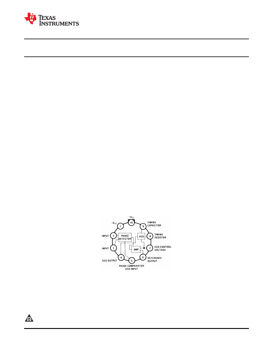
Connection Diagram
TO-100 Package
See Package Number LME
1
Please be aware that an important notice concerning availability, standard warranty, and use in critical applications of
Texas Instruments semiconductor products and disclaimers thereto appears at the end of this data sheet.
2
All trademarks are the property of their respective owners.
PRODUCTION DATA information is current as of publication date.
Copyright © 1999-2013, Texas Instruments Incorporated
Products conform to specifications per the terms of the Texas
Instruments standard warranty. Production processing does not
necessarily include testing of all parameters.
OBSOLETE
SNOSBU1B - MAY 1999 - REVISED APRIL 2013
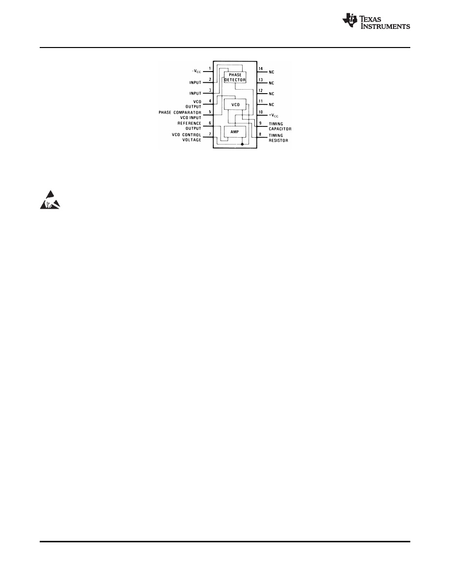
Dual-in-Line Package
PDIP
See Package Number NFF
These devices have limited built-in ESD protection. The leads should be shorted together or the device placed in conductive foam
during storage or handling to prevent electrostatic damage to the MOS gates.
2
Copyright © 1999-2013, Texas Instruments Incorporated
Product Folder Links:
OBSOLETE
SNOSBU1B - MAY 1999 - REVISED APRIL 2013
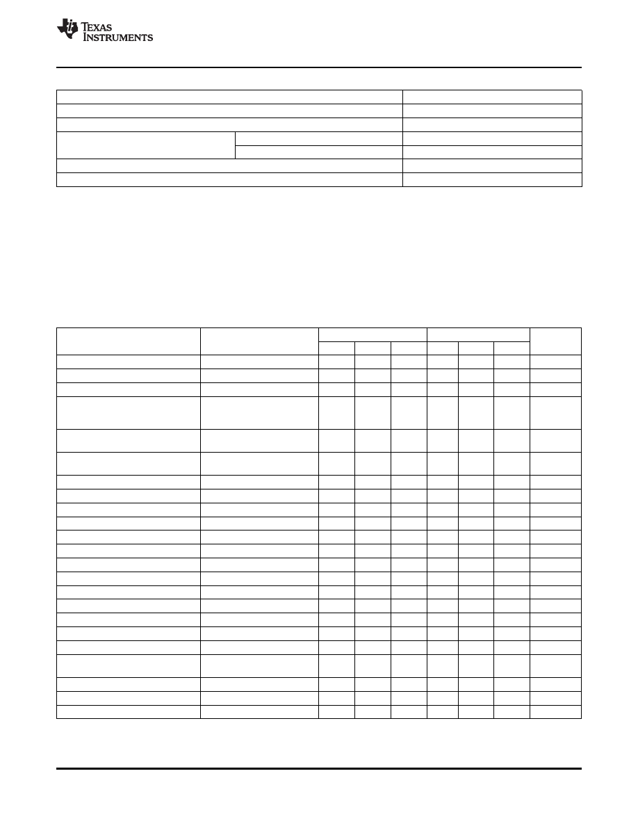
Absolute Maximum Ratings
(1) (2)
Supply Voltage
±12V
Power Dissipation
(3)
1400 mW
Differential Input Voltage
±1V
Operating Temperature Range
LM565H
-
55 °C to +125 °C
LM565CN
0 °C to +70 °C
Storage Temperature Range
-
65 °C to +150 °C
Lead Temperature (Soldering, 10 sec.)
260 °C
(1)
Absolute Maximum Ratings indicate limits beyond which damage to the device may occur. Operating Ratings indicate conditions for
which the device is functional, but do not ensure specific performance limits. Electrical Characteristics state DC and AC electrical
specifications under particular test conditions which ensure specific performance limits. This assumes that the device is within the
Operating Ratings. Specifications are not ensured for parameters where no limit is given, however, the typical value is a good indication
of device performance.
(2)
If Military/Aerospace specified devices are required, please contact the Texas Instruments Sales Office/ Distributors for availability and
specifications.
(3)
The maximum junction temperature of the LM565 and LM565C is +150 °C. For operation at elevated temperatures, devices in the TO-5
package must be derated based on a thermal resistance of +150 °C/W junction to ambient or +45 °C/W junction to case. Thermal
resistance of the dual-in-line package is +85 °C/W.
Electrical Characteristics
AC Test Circuit, T
A
= 25 °C, V
CC
= ±6V
LM565
LM565C
Parameter
Conditions
Units
Min
Typ
Max
Min
Typ
Max
Power Supply Current
8.0
12.5
8.0
12.5
mA
Input Impedance (Pins 2, 3)
-
4V < V
2
, V
3
< 0V
7
10
5
k
Ω
VCO Maximum Operating Frequency C
o
= 2.7 pF
300
500
250
500
kHz
VCO Free-Running Frequency
C
o
= 1.5 nF
R
o
= 20 k
Ω
-
10
0
+10
-
30
0
+30
%
f
o
= 10 kHz
Operating Frequency
-
100
-
200
ppm/ °C
Temperature Coefficient
Frequency Drift with
0.1
1.0
0.2
1.5
%/V
Supply Voltage
Triangle Wave Output Voltage
2
2.4
3
2
2.4
3
V
p-p
Triangle Wave Output Linearity
0.2
0.5
%
Square Wave Output Level
4.7
5.4
4.7
5.4
V
p-p
Output Impedance (Pin 4)
5
5
k
Ω
Square Wave Duty Cycle
45
50
55
40
50
60
%
Square Wave Rise Time
20
20
ns
Square Wave Fall Time
50
50
ns
Output Current Sink (Pin 4)
0.6
1
0.6
1
mA
VCO Sensitivity
f
o
= 10 kHz
6600
6600
Hz/V
Demodulated Output Voltage (Pin 7)
±10% Frequency Deviation
250
300
400
200
300
450
mV
p-p
Total Harmonic Distortion
±10% Frequency Deviation
0.2
0.75
0.2
1.5
%
Output Impedance (Pin 7)
3.5
3.5
k
Ω
DC Level (Pin 7)
4.25
4.5
4.75
4.0
4.5
5.0
V
Output Offset Voltage
30
100
50
200
mV
|V
7
-
V
6
|
Temperature Drift of |V
7
-
V
6
|
500
500
μ
V/ °C
AM Rejection
30
40
40
dB
Phase Detector Sensitivity K
D
0.68
0.68
V/radian
Copyright © 1999-2013, Texas Instruments Incorporated
3
Product Folder Links:
OBSOLETE
SNOSBU1B - MAY 1999 - REVISED APRIL 2013
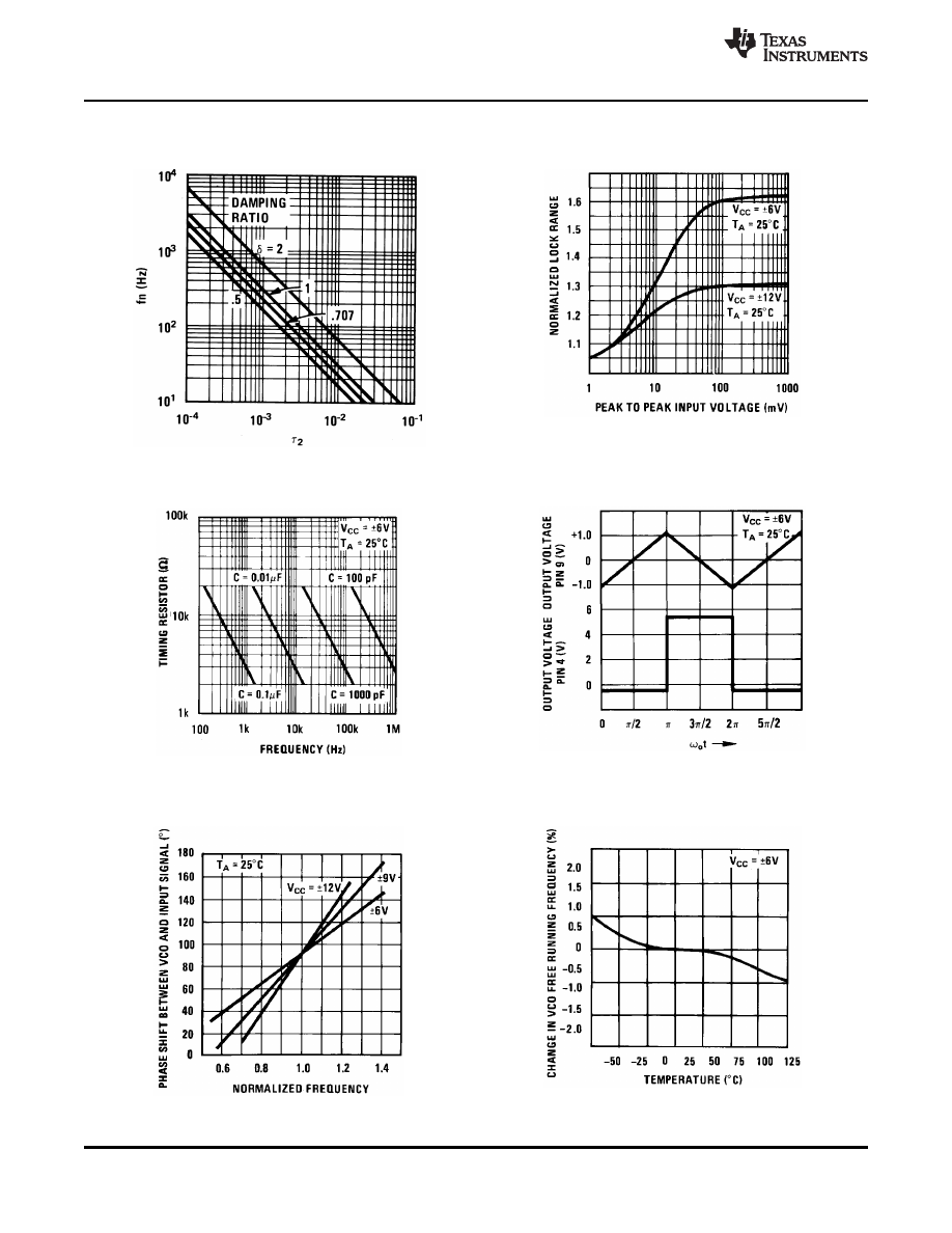
Typical Performance Characteristics
Power Supply Current as a
Lock Range as a Function
Function of Supply Voltage
of Input Voltage
Figure 1.
Figure 2.
Oscillator Output
VCO Frequency
Waveforms
Figure 3.
Figure 4.
Phase Shift
vs
VCO Frequency as a
Frequency
Function of Temperature
Figure 5.
Figure 6.
4
Copyright © 1999-2013, Texas Instruments Incorporated
Product Folder Links:
OBSOLETE
SNOSBU1B - MAY 1999 - REVISED APRIL 2013
Typical Performance Characteristics (continued)
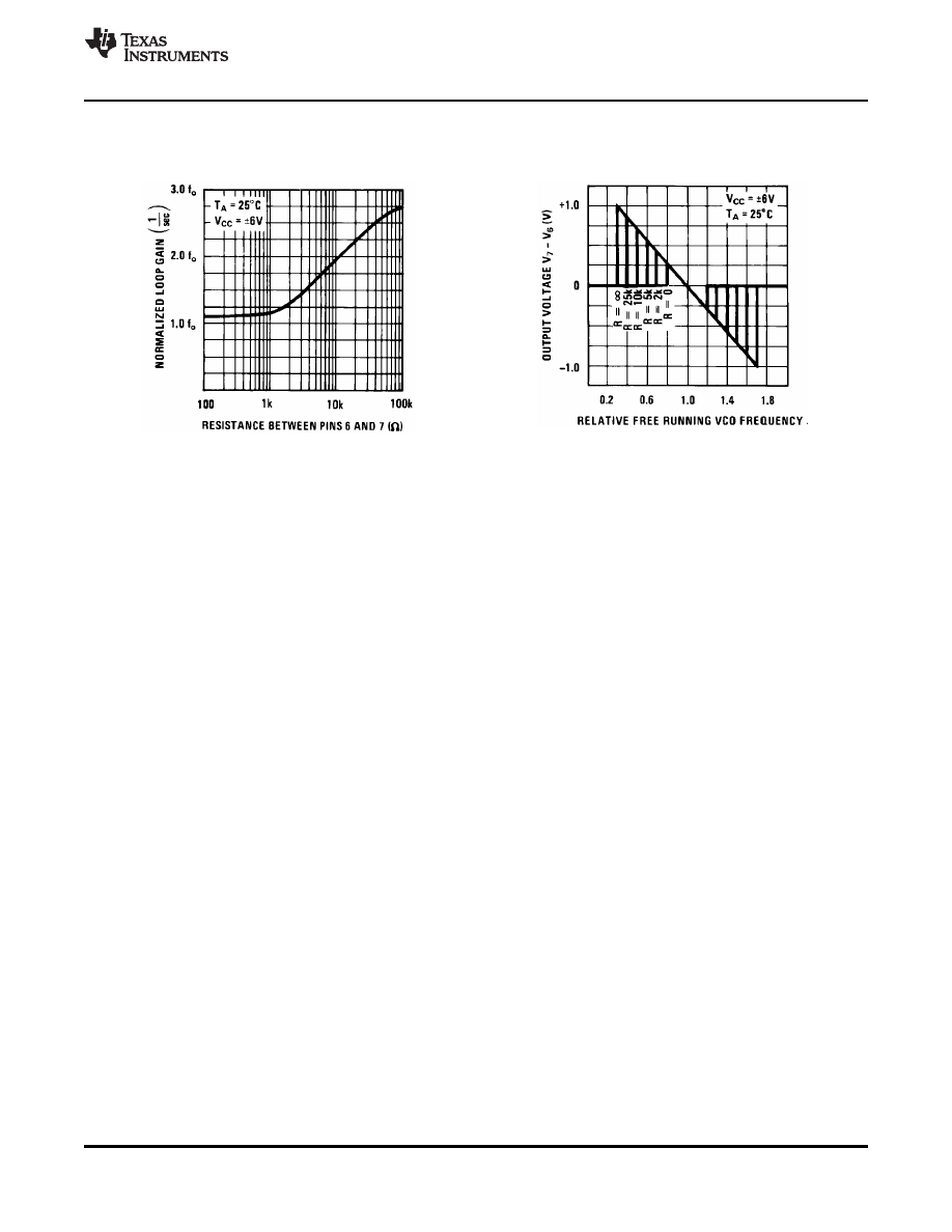
Loop Gain
vs
Load
Hold in Range as a
Resistance
Function of R
6-7
Figure 7.
Figure 8.
Copyright © 1999-2013, Texas Instruments Incorporated
5
Product Folder Links:
OBSOLETE
SNOSBU1B - MAY 1999 - REVISED APRIL 2013
Schematic Diagram
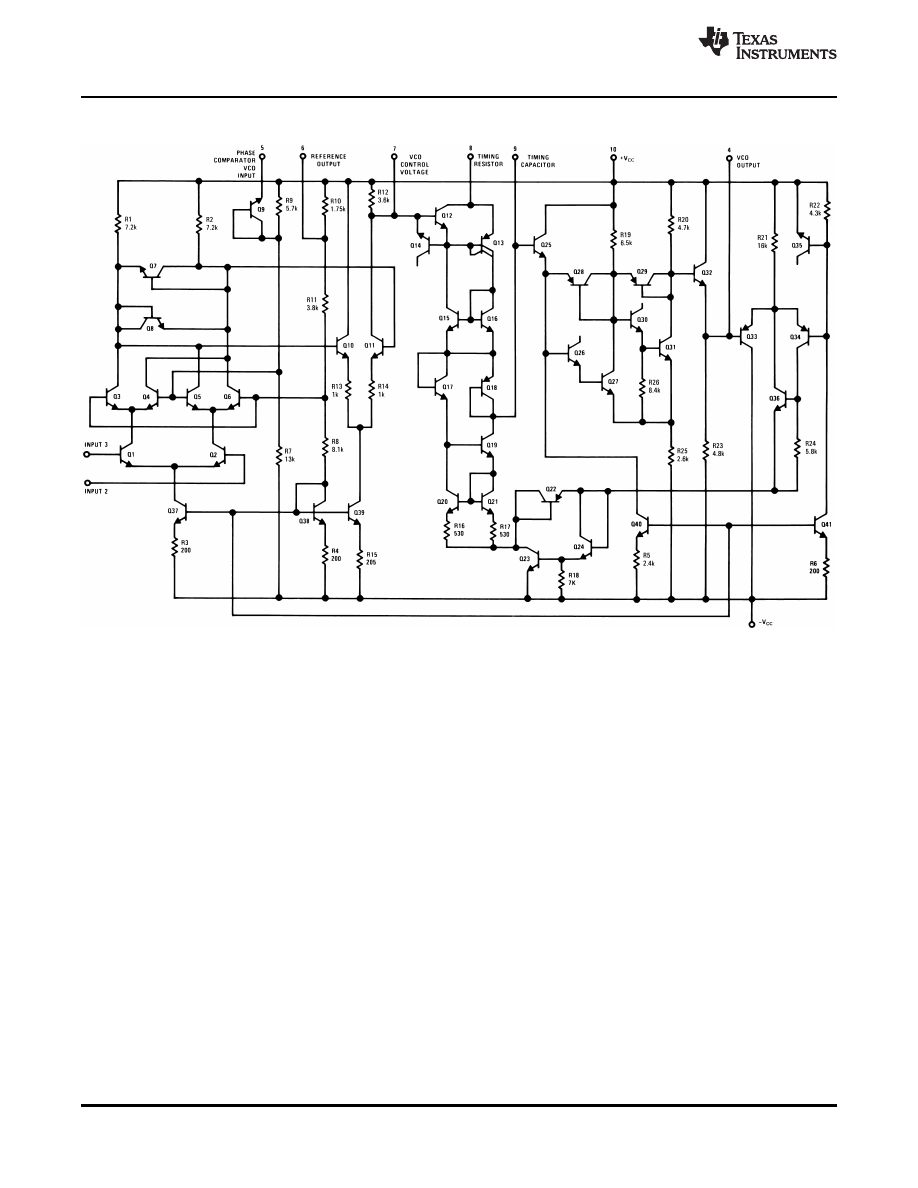
Figure 9. Schematic Diagram
6
Copyright © 1999-2013, Texas Instruments Incorporated
Product Folder Links:
OBSOLETE
SNOSBU1B - MAY 1999 - REVISED APRIL 2013
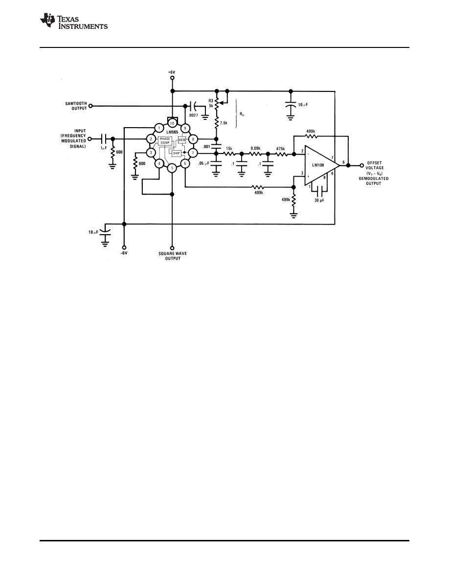
AC Test Circuit
Note: S
1
open for output offset voltage (V
7
-
V
6
) measurement.
Figure 10. AC Test Circuit
Copyright © 1999-2013, Texas Instruments Incorporated
7
Product Folder Links:
OBSOLETE
SNOSBU1B - MAY 1999 - REVISED APRIL 2013
Typical Applications
Figure 11. 2400 Hz Synchronous AM Demodulator
8
Copyright © 1999-2013, Texas Instruments Incorporated
Product Folder Links:
OBSOLETE
SNOSBU1B - MAY 1999 - REVISED APRIL 2013
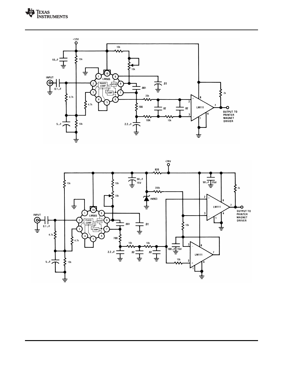
Figure 12. FSK Demodulator (2025-2225 cps)
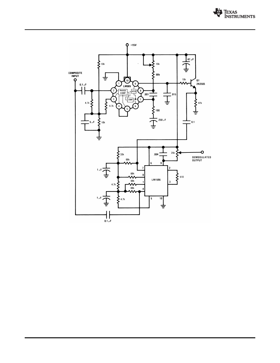
Figure 13. FSK Demodulator with DC Restoration
Copyright © 1999-2013, Texas Instruments Incorporated
9
Product Folder Links:
OBSOLETE
SNOSBU1B - MAY 1999 - REVISED APRIL 2013
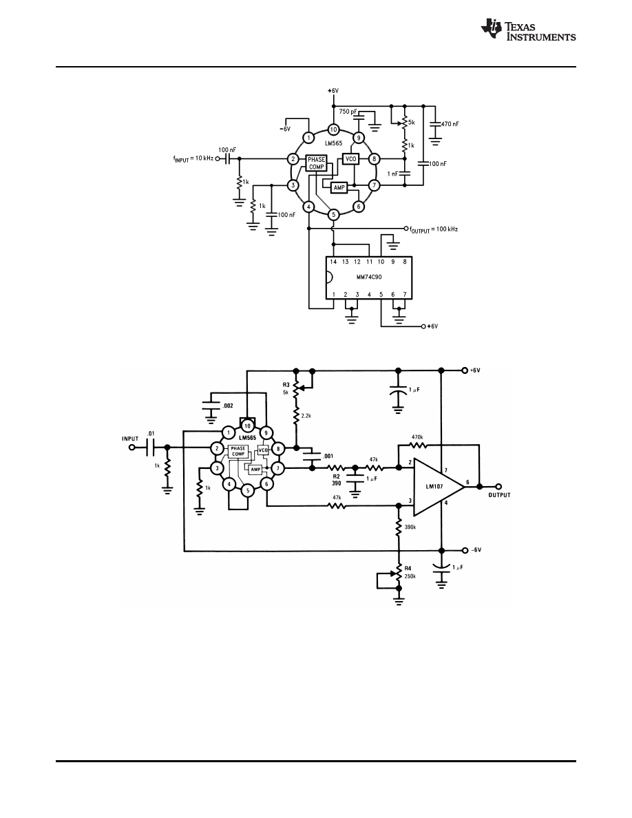
Figure 14. Frequency Multiplier (×10)
Figure 15. IRIG Channel 13 Demodulator
10
Copyright © 1999-2013, Texas Instruments Incorporated
Product Folder Links:
OBSOLETE
SNOSBU1B - MAY 1999 - REVISED APRIL 2013
APPLICATIONS INFORMATION
In designing with phase locked loops such as the LM565, the important parameters of interest are:
FREE RUNNING FREQUENCY
(1)
LOOP GAIN: relates the amount of phase change between the input signal and the VCO signal for a shift in input
signal frequency (assuming the loop remains in lock). In servo theory, this is called the †śvelocity error coefficient.†ť
(2)
The loop gain of the LM565 is dependent on supply voltage, and may be found from:
(3)
f
o
= VCO frequency in Hz
V
c
= total supply voltage to circuit
Loop gain may be reduced by connecting a resistor between pins 6 and 7; this reduces the load impedance on
the output amplifier and hence the loop gain.
HOLD IN RANGE: the range of frequencies that the loop will remain in lock after initially being locked.
where
•
f
o
= free running frequency of VCO
•
V
c
= total supply voltage to the circuit
(4)
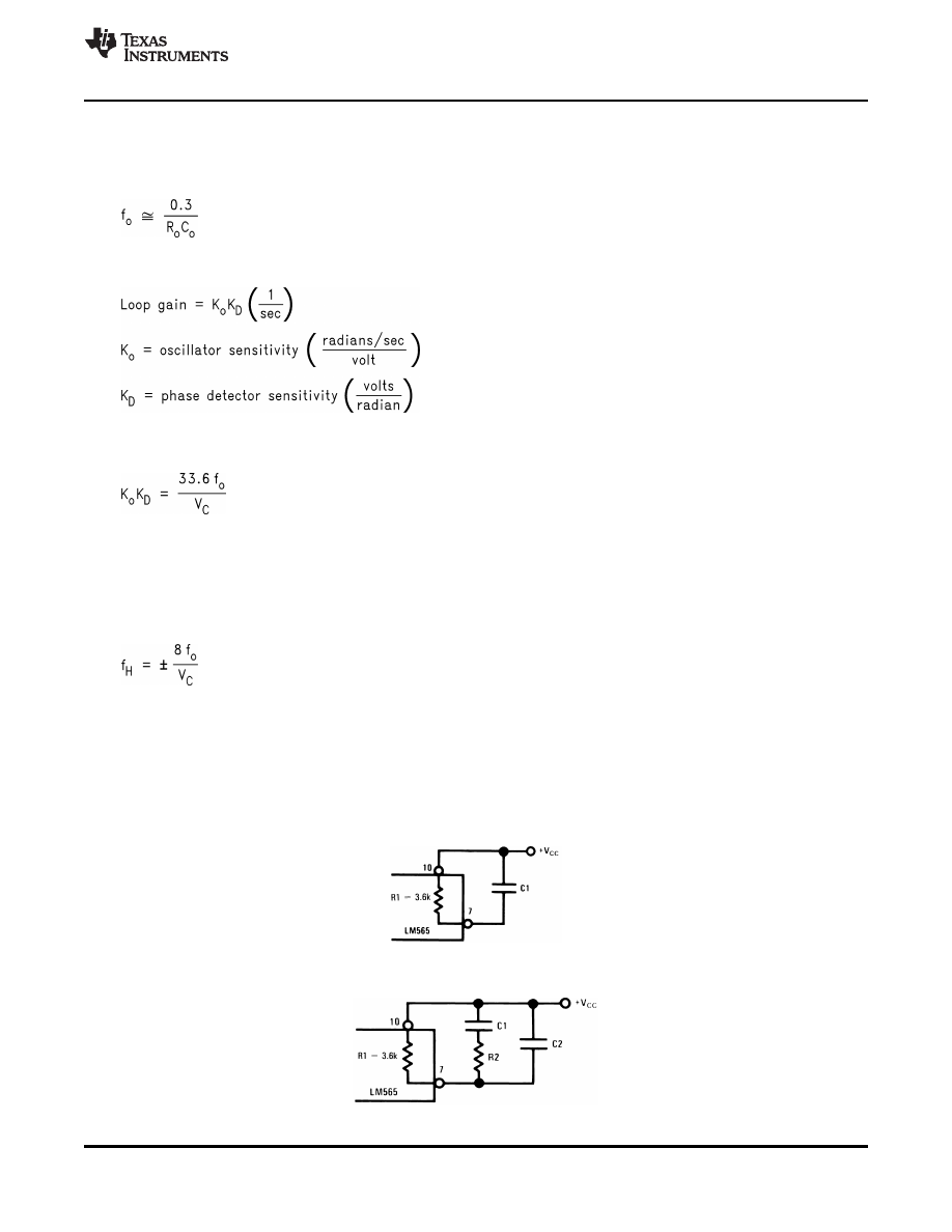
THE LOOP FILTER
In almost all applications, it will be desirable to filter the signal at the output of the phase detector (pin 7); this
filter may take one of two forms:
Figure 16. Simple Lead Filter
Figure 17. Lag-Lead Filter
Copyright © 1999-2013, Texas Instruments Incorporated
11
Product Folder Links:
OBSOLETE
SNOSBU1B - MAY 1999 - REVISED APRIL 2013
A simple lag filter may be used for wide closed loop bandwidth applications such as modulation following where
the frequency deviation of the carrier is fairly high (greater than 10%), or where wideband modulating signals
must be followed.
The natural bandwidth of the closed loop response may be found from:
(5)
Associated with this is a damping factor:
(6)
For narrow band applications where a narrow noise bandwidth is desired, such as applications involving tracking
a slowly varying carrier, a lead lag filter should be used. In general, if 1/R
1
C
1
< K
o
K
D
, the damping factor for the
loop becomes quite small resulting in large overshoot and possible instability in the transient response of the
loop. In this case, the natural frequency of the loop may be found from
(7)
R
2
is selected to produce a desired damping factor
δ
, usually between 0.5 and 1.0. The damping factor is found
from the approximation:
δ •‰Š Ď€ Ď„
2
f
n
(8)
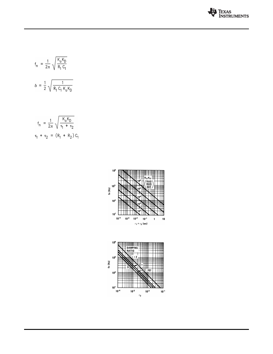
These two equations are plotted for convenience.
Figure 18. Filter Time Constant vs Natural Frequency
Figure 19. Damping Time Constant vs Natural Frequency
Capacitor C
2
should be much smaller than C
1
since its function is to provide filtering of carrier. In general C
2
≤
0.1 C
1
.
12
Copyright © 1999-2013, Texas Instruments Incorporated
Product Folder Links:

OBSOLETE
SNOSBU1B - MAY 1999 - REVISED APRIL 2013
REVISION HISTORY
Changes from Revision A (April 2013) to Revision B
Page
•
Changed layout of National Data Sheet to TI format ..........................................................................................................
Copyright © 1999-2013, Texas Instruments Incorporated
13
Product Folder Links:

IMPORTANT NOTICE
Texas Instruments Incorporated and its subsidiaries (TI) reserve the right to make corrections, enhancements, improvements and other
changes to its semiconductor products and services per JESD46, latest issue, and to discontinue any product or service per JESD48, latest
issue. Buyers should obtain the latest relevant information before placing orders and should verify that such information is current and
complete. All semiconductor products (also referred to herein as †ścomponents†ť) are sold subject to TI’s terms and conditions of sale
supplied at the time of order acknowledgment.
TI warrants performance of its components to the specifications applicable at the time of sale, in accordance with the warranty in TI’s terms
and conditions of sale of semiconductor products. Testing and other quality control techniques are used to the extent TI deems necessary
to support this warranty. Except where mandated by applicable law, testing of all parameters of each component is not necessarily
performed.
TI assumes no liability for applications assistance or the design of Buyers’ products. Buyers are responsible for their products and
applications using TI components. To minimize the risks associated with Buyers’ products and applications, Buyers should provide
adequate design and operating safeguards.
TI does not warrant or represent that any license, either express or implied, is granted under any patent right, copyright, mask work right, or
other intellectual property right relating to any combination, machine, or process in which TI components or services are used. Information
published by TI regarding third-party products or services does not constitute a license to use such products or services or a warranty or
endorsement thereof. Use of such information may require a license from a third party under the patents or other intellectual property of the
third party, or a license from TI under the patents or other intellectual property of TI.
Reproduction of significant portions of TI information in TI data books or data sheets is permissible only if reproduction is without alteration
and is accompanied by all associated warranties, conditions, limitations, and notices. TI is not responsible or liable for such altered
documentation. Information of third parties may be subject to additional restrictions.
Resale of TI components or services with statements different from or beyond the parameters stated by TI for that component or service
voids all express and any implied warranties for the associated TI component or service and is an unfair and deceptive business practice.
TI is not responsible or liable for any such statements.
Buyer acknowledges and agrees that it is solely responsible for compliance with all legal, regulatory and safety-related requirements
concerning its products, and any use of TI components in its applications, notwithstanding any applications-related information or support
that may be provided by TI. Buyer represents and agrees that it has all the necessary expertise to create and implement safeguards which
anticipate dangerous consequences of failures, monitor failures and their consequences, lessen the likelihood of failures that might cause
harm and take appropriate remedial actions. Buyer will fully indemnify TI and its representatives against any damages arising out of the use
of any TI components in safety-critical applications.
In some cases, TI components may be promoted specifically to facilitate safety-related applications. With such components, TI’s goal is to
help enable customers to design and create their own end-product solutions that meet applicable functional safety standards and
requirements. Nonetheless, such components are subject to these terms.
No TI components are authorized for use in FDA Class III (or similar life-critical medical equipment) unless authorized officers of the parties
have executed a special agreement specifically governing such use.
Only those TI components which TI has specifically designated as military grade or †śenhanced plastic†ť are designed and intended for use in
military/aerospace applications or environments. Buyer acknowledges and agrees that any military or aerospace use of TI components
which have not been so designated is solely at the Buyer's risk, and that Buyer is solely responsible for compliance with all legal and
regulatory requirements in connection with such use.
TI has specifically designated certain components as meeting ISO/TS16949 requirements, mainly for automotive use. In any case of use of
non-designated products, TI will not be responsible for any failure to meet ISO/TS16949.
Products
Applications
Audio
Automotive and Transportation
Amplifiers
Communications and Telecom
Data Converters
Computers and Peripherals
DLP ® Products
Consumer Electronics
DSP
Energy and Lighting
Clocks and Timers
Industrial
Interface
Medical
Logic
Security
Power Mgmt
Space, Avionics and Defense
Microcontrollers
Video and Imaging
RFID
OMAP Applications Processors
TI E2E Community
Wireless Connectivity
Mailing Address: Texas Instruments, Post Office Box 655303, Dallas, Texas 75265
Copyright © 2013, Texas Instruments Incorporated
Document Outline
