| Secciones |
|---|
| Foros Electrónica |
|
|
| Boletines de correo |
 |
M
P
SA93 PNP High V
o
lt
age Am
plif
ier
© 2007 Fairchild Semiconductor Corporation
www.fairchildsemi.com
MPSA93 Rev. 1.0.0
1
September 2007
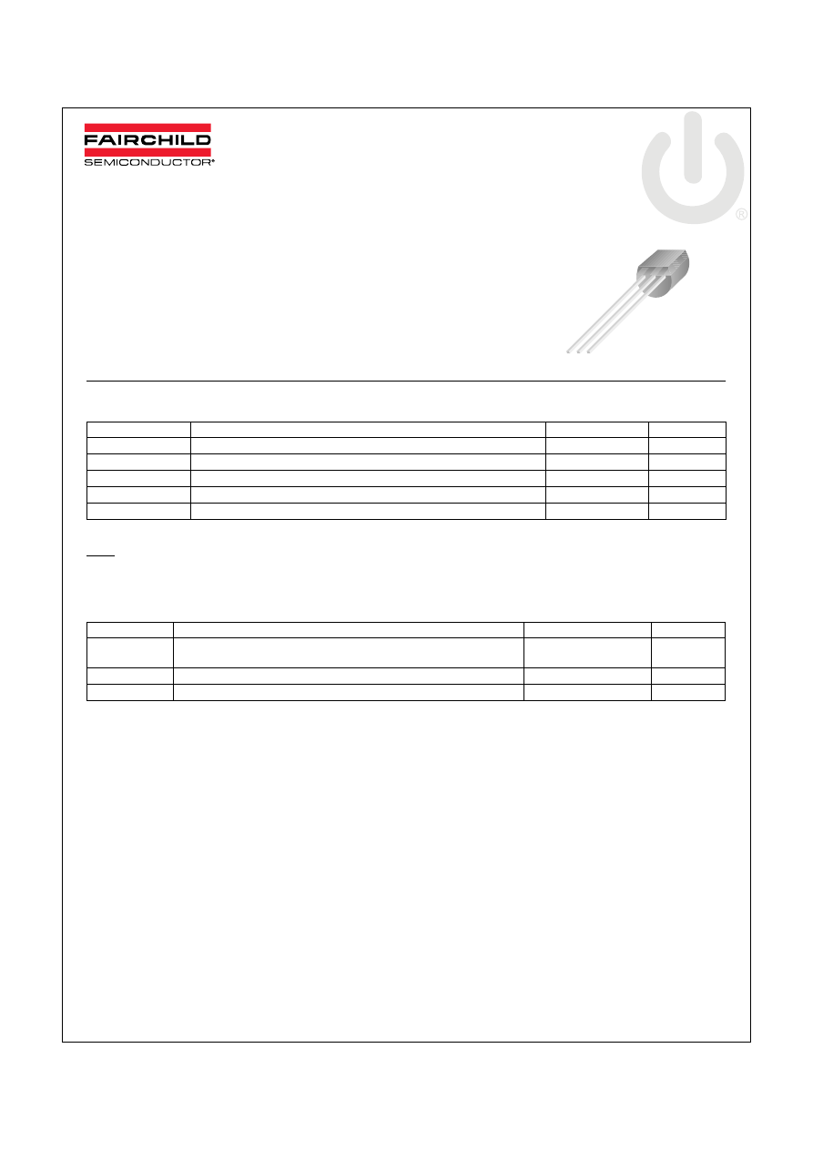
MPSA93
PNP High Voltage Amplifier
This device is designed for high voltage driver applications.
Sourced from Process 76.
Absolute Maximum Ratings
T
C
=25
°C unless otherwise noted
* These ratings are limiting values above which the serviceability of any semiconductor device may be impaired.
NOTES:
1) These ratings are based on a maximum junction temperature of 150 degrees C.
2) These are steady state limits. The factory should be consulted on applications involving pulsed or low duty cycle operations.
Thermal Characteristics
T
a
=25
°C unless otherwise noted
* Device mounted on FR-4 PCB 1.6 X 1.6 X 0.06.
Symbol
Parameter
Value
Units
V
CEO
Collector-Emitter Voltage
200
V
V
CBO
Collector-Base Voltage
200
V
V
EBO
Emitter-Base Voltage
5
V
I
C
Collector Current (DC)
500
mA
T
J
, T
STG
Operating and Storage Junction Temperature Range
-55 ~ +150
°C
Symbol
Parameter
Max.
Units
P
D
Total Device Dissipation
Derate above 25
°C
625
5.0
mW
mW/
°C
R
ΘJC
Thermal Resistance, Junction to Case
83.3
°C/W
R
ΘJA
Thermal Resistance, Junction to Ambient
200
°C/W
1. Collector 2. Base 3. Emitter
TO-92
1
M
P
SA93 PNP High V
o
lt
age Am
plif
ier
© 2007 Fairchild Semiconductor Corporation
www.fairchildsemi.com
MPSA93 Rev. 1.0.0
2
Electrical Characteristics
T
C
=25
°C unless otherwise noted
* Pulse Test: Pulse Width 300 s, Duty Cycle 2.0%
Notes:
1) All voltages (V) and currents (A) are negative polarity for PNP transistors.
Symbol
Parameter
Test Condition
Min.
Typ.
Max.
Units
Off Characteristics
V
(BR)CBO
Collector-Base Breakdown Voltage
I
C
= 100
μA, I
E
= 0
200
V
V
(BR)CEO
Collector-Emitter Breakdown Voltage*
I
C
= 1 mA, I
B
= 0
200
V
V
(BR)EBO
Emitter-Base Breakdown Voltage
I
E
= 100
μA, I
C
= 0
5
V
I
EBO
Emitter Cut-off Current
V
EB
= 3V, I
C
= 0
0.1
μA
I
CBO
Collector Cut-off Current
V
CB
= 200V, I
E
= 0
0.25
μA
On Characteristics
h
FE
DC Current Gain
V
CE
= 10V, I
C
= 1mA
V
CE
= 10V, I
C
= 10mA
V
CE
= 10V, I
C
= 30mA
25
40
25
V
CE
(sat)
Collector-Emitter Saturation Voltage
I
C
= 20 mA, I
B
= 2 mA
0.4
V
V
BE
(sat)
Base-Emitter Saturation Voltage
I
C
= 20 mA, I
B
= 2 mA
0.9
V
Small Signal Characteristics
C
cb
Collector-Base Capacitance
V
CB
= 20 V, I
E
= 0, f = 1.0 MHz
8
pF
f
T
Current Gain Bandwidth Product
V
CE
= 5.0V, I
C
= 10mA, f = 100MHz
50
MHz
MPSA9
3
PNP High
V
o
lt
a
g
e Amp
lifier
MP
SA9
3
TRADEMARKS
The following are registered and unregistered trademarks and service marks Fairchild Semiconductor owns or is authorized to use and
is not intended to be an exhaustive list of all such trademarks.
DISCLAIMER
FAIRCHILD SEMICONDUCTOR RESERVES THE RIGHT TO MAKE CHANGES WITHOUT FURTHER NOTICE TO ANY PRODUCTS
HEREIN TO IMPROVE RELIABILITY, FUNCTION, OR DESIGN. FAIRCHILD DOES NOT ASSUME ANY LIABILITY ARISING OUT OF
THE APPLICATION OR USE OF ANY PRODUCT OR CIRCUIT DESCRIBED HEREIN; NEITHER DOES IT CONVEY ANY LICENSE
UNDER ITS PATENT RIGHTS, NOR THE RIGHTS OF OTHERS. THESE SPECIFICATIONS DO NOT EXPAND THE TERMS OF
FAIRCHILDS WORLDWIDE TERMS AND CONDITIONS, SPECIFICALLY THE WARRANTY THEREIN, WHICH COVERS THESE
PRODUCTS.
LIFE SUPPORT POLICY
FAIRCHILDS PRODUCTS ARE NOT AUTHORIZED FOR USE AS CRITICAL COMPONENTS IN LIFE SUPPORT DEVICES OR
SYSTEMS WITHOUT THE EXPRESS WRITTEN APPROVAL OF FAIRCHILD SEMICONDUCTOR CORPORATION.
As used herein:
1. Life support devices or systems are devices or systems
which, (a) are intended for surgical implant into the body, or
(b) support or sustain life, and (c) whose failure to perform
when properly used in accordance with instructions for use
provided in the labeling, can be reasonably expected to result
in significant injury to the user.
2.
A critical component is any component of a life support
device or system whose failure to perform can be reasonably
expected to cause the failure of the life support device or
system, or to affect its safety or effectiveness.
PRODUCT STATUS DEFINITIONS
Definition of Terms
ACEx
®
Build it Now™
CorePLUS™
CROSSVOLT™
CTL™
Current Transfer Logic™
EcoSPARK
®
Fairchild
®
Fairchild Semiconductor
®
FACT Quiet Series™
FACT
®
FAST
®
FastvCore™
FPS™
FRFET
®
Global Power Resource
SM
Green FPS™
Green FPS™ e-Series™
GTO™
i-Lo™
IntelliMAX™
ISOPLANAR™
MegaBuck™
MICROCOUPLER™
MicroFET™
MicroPak™
Motion-SPM™
OPTOLOGIC
®
OPTOPLANAR
®
®
PDP-SPM™
Power220
®
Power247
®
POWEREDGE
®
Power-SPM™
PowerTrench
®
Programmable Active Droop™
QFET
®
QS™
QT Optoelectronics™
Quiet Series™
RapidConfigure™
SMART START™
SPM
®
STEALTH™
SuperFET™
SuperSOT™-3
SuperSOT™-6
SuperSOT™-8
SyncFET™
The Power Franchise
®
TinyBoost™
TinyBuck™
TinyLogic
®
TINYOPTO™
TinyPower™
TinyPWM™
TinyWire™
µSerDes™
UHC
®
UniFET™
VCX™
Datasheet Identification
Product Status
Definition
Advance Information
Formative or In Design
This datasheet contains the design specifications for product development.
Specifications may change in any manner without notice.
Preliminary
First Production
This datasheet contains preliminary data; supplementary data will be pub-
lished at a later date. Fairchild Semiconductor reserves the right to make
changes at any time without notice to improve design.
No Identification Needed
Full Production
This datasheet contains final specifications. Fairchild Semiconductor reserves
the right to make changes at any time without notice to improve design.
Obsolete
Not In Production
This datasheet contains specifications on a product that has been discontin-
ued by Fairchild semiconductor. The datasheet is printed for reference infor-
mation only.
Rev. I30
© 2007 Fairchild Semiconductor Corporation
www.fairchildsemi.com
MPSA93 Rev. 1.0.0
3

